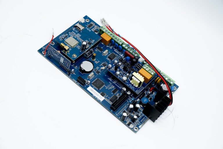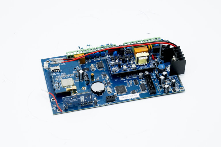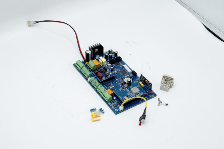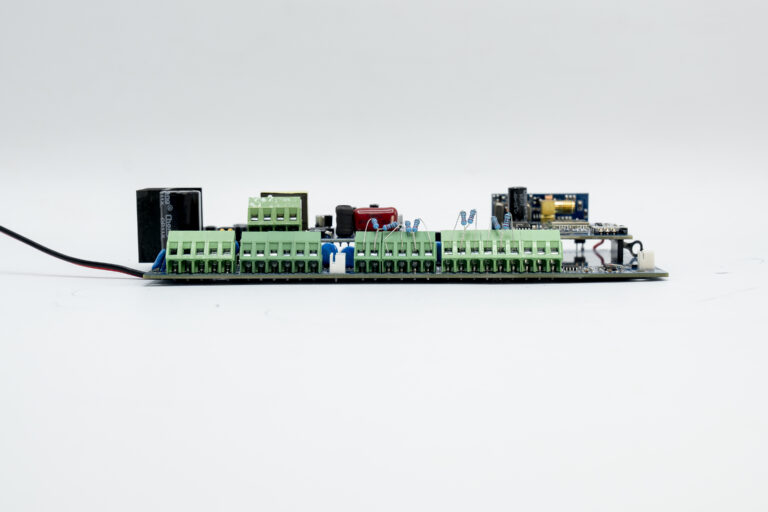


System PCB
| Attribute | Details |
|---|---|
| Network | GPRS, GSM, LAN, PSTN |
| Brand Name | Impaxx |
| Usage | Auto |
| Certificate | CE, FCC, RoHS |
| GSM band | 850MHz, 900MHz, 1800MHz, 1900MHz |
| Working frequency | 433.92MHz |
| Power | AV 110-240V |
| Built-in battery | 3.7V/800mAh |
| Material | Plastic |
| Warranty | 2 Years |
| WIFI frequency | 2.4G |
| Working temperature | -10℃ to +50℃ |
| Selling Units | Single item |
| Single package size | 22X16X9.5 cm |
| Single gross weight | 2.000 kg |
1. Panel Connection
Panel should be strictly and separately connected with wires of different colors for different uses as the wiring diagram describes. Firstly, according to the installation and construction plan, cable wires should be drawn to the installation site, and connected with panel correctly and accordingly. Before connecting wires, the joint of cable wires is required to be peeled and the length of bare copper should be accorded with the wire interface depth. If too short, it is easy to cause bad connection; if too long, it is easy to cause short circuit. If one interface is connected with two wires or more, it requires that these bare copper wires should be tightened, inserted into the interface, and put on the screw, which can bear certain tension.
2. SIM Card Slot
SIM card slot is used to install SIM card with GSM signal. Only each panel insert a SIM card can GSM module normally work. Note: When installing the SIM card, please do not touch other components in circuit board in order to avoid damaging panel caused by static electricity and to avoid influencing system’s normal working.
Warning: If user inserts SIM card when power is on, it will damage SIM card perpetually. Please remember to cut off any powers including the AC power and storage battery power before installation.
3. SMA Plug
Connect GSM sucker antenna with SMA plug put them on SMA plug base and tighten the screw of SMA plug clockwise. Note: the quality of GSM antenna will directly influence the GSM signal, GSM power, and alarm transmission speed. Please ensure to tighten the screw of SMA plug.
4. AC Power Connection: AC & AC
AC power source is a 16V/15A, 50/60Hz transformer. The secondary voltage of transformer should be connected with AC interface. Do not connect the primary voltage of transformer with power source or with circuit which has short circuit protection device. Only all wires are connected, AC power can be put on.
Note: if the time of AC power off is beyond preset check time, the panel will prompt AC power off. If the phone alarm is enabled when system has fault, then panel will send the power off report to user. If the AC power recovery is beyond the preset check time, then panel will send AC recovery report to user.
5. Battery Installation
Panel must install storage battery (as Figure 3) to make sure panel normal working when panel power is cut off. The red wire should be connected with battery positive side, while black wire with negative side. The panel adopts 12V/7Ah lead-acid battery and prohibits using non-rechargeable or non-lead-acid battery. It is suggested that battery should be changed every two year. Note: when battery voltage is lower than 11.6V, then panel will prompt low power. If phone alarm is enabled when system hasfault, then panel will send low power report to user. When low voltage time is beyond 2h, then panel will cut off battery supply to protect battery.
Please do not install battery before connecting all wires correctly.
Recommendusethe Kanglida company of 12V7AH-SC lead-acid battery to supply powertohost
6. Siren output connection: BELL & GND & PGM
The interface BELL is siren positive output port, when panel alarms, it can provide DC power 10. 9V-14.5V for siren. And it provides over current protection for circuit with self-recovered fuse wire (F1). When current is beyond 350mA, the fuse wire (F1) will auto-cut off the connection between panel and siren. Please notice the siren connection polarity :connect Bell with positive side, while GND with negative side as (picture 3) show.
The interface PGM is siren negative signal, when panel alarms, it can support “Ground”signal. it need to notice that this interface can not be used as Ground” when connect to siren. connect AUX with positive side, while PGM with negative side as (picture 4) show. Attention: when PGM connect relay, connect relay one side with AUX, other side with PGM as (picture 5) show
4. AC Power Connection: AC & AC
AC power source is a 16V/15A, 50/60Hz transformer. The secondary voltage of transformer should be connected with AC interface. Do not connect the primary voltage of transformer with power source or with circuit which has short circuit protection device. Only all wires are connected, AC power can be put on.
Note: if the time of AC power off is beyond preset check time, the panel will prompt AC power off. If the phone alarm is enabled when system has fault, then panel will send the power off report to user. If the AC power recovery is beyond the preset check time, then panel will send AC recovery report to user.
- 5. Battery Installation
Panel must install storage battery (as Figure 3) to make sure panel normal working when panel power is cut off. The red wire should be connected with battery positive side, while black wire with negative side. The panel adopts 12V/7Ah lead-acid battery and prohibits using non-rechargeable or non-lead-acid battery. It is suggested that battery should be changed every two year. Note: when battery voltage is lower than 11.6V, then panel will prompt low power. If phone alarm is enabled when system hasfault, then panel will send low power report to user. When low voltage time is beyond 2h, then panel will cut off battery supply to protect battery. - Please do not install battery before connecting all wires correctly.
- Recommendusethe Kanglida company of 12V7AH-SC lead-acid battery to supply powertohost
6. Siren output connection: BELL & GND & PGM
The interface BELL is siren positive output port, when panel alarms, it can provide DC power 10. 9V-14.5V for siren. And it provides over current protection for circuit with self-recovered fuse wire (F1). When current is beyond 350mA, the fuse wire (F1) will auto-cut off the connection between panel and siren. Please notice the siren connection polarity :connect Bell with positive side, while GND with negative side as (picture 3) show.
The interface PGM is siren negative signal, when panel alarms, it can support “Ground”signal. it need to notice that this interface can not be used as Ground” when connect to siren. connect AUX with positive side, while PGM with negative side as (picture 4) show. Attention: when PGM connect relay, connect relay one side with AUX, other side with PGM as (picture 5) show
7. Assist Power Connection: AUX & GND
AUX & GND belongs to non-off interface, which can provide 10,9V-14,5V/350mA DC power for wired accessories and also provide over current protection with self-recovered fuse wire (F2) for circuit.
8. Module Wires Connection: AUX & GND & DAT
AUX & GND interface provides power for module, and DAT is a data interface to connect panel with module. The system can connect with octuple zone module and octuple relay module and so on. When the module wire is 22AWG (0.643mm) copper wire, then the longest distance is 200m.
Note: module has priority to adopt the panel power. When the panel power is not enough, then uses the DC power. When module provides power for external source, the external source negative side should be connected with panel source output negative side.
9. Wires keyboard connection:AUX & GND & DAT
This port can directly connect wires keypad as prevent stay interface. the module wire is 22AWG (0.643mm) copper wire, then the longest distance is 200m.
10. Wired Zone Connection: Z1-Z8 & GND
Z1-Z8 & GND is the eight zone interfaces. Z1-Z4 interface is to connect with zone loop positive side; C interface is to connect with zone loop negative side. Please especially notice the connection polarity to avoid damaging related devices. When connecting with manual switch or foot switch, user can ignore its polarity.
Each zone loop type can be programmed as “cut-off alarm”, “closed alarm” and “end of line”. If zone loop type is programmed as “cut-off alarm” or “closed alarm”, then the detector interface can be connected with zone loop interface. If zone loop interface is programmed as “end of line”, then 2.2K resistance should be connected with end of loop (including zone loop). The connection principle: normal open detector should be parallel connected with 2.2K resistance; normal close detector should be connected with 2.2 K resistance in series. In order to avoid damaging loop wires (be cut off or be cut out), it is better to program zone loop as “end of line”.
If lead wires and cable wires are connected with the same interface, then it is necessary to tighten and screw them together, then insert them into the interface. If it is required that lead wires are wire-wrap connected with cable wires, then they should be soldered after wire-wrap connection. In addition, resistance lead wires should be shorter as far as possible to avoid causing short
circuit. If it needs panel to offer power to detector, then the positive side and negative side of detector power input terminal should be respectively connected with AUX and C interface.
11. Relay Connection: NO & COM & NC
NO & COM & NC is programming linkage output interface. Various events and alarms will drive relay to output. NC is normal close interface; NO is normal open interface; COM is common interface. The interface can load 1A 120VAC/24VDC. If the power of controlled electronical equipments is beyond loads, user should develop a big power relay to avoid damaging panel.
12.Firmware Update interface: UPDATD
This port used by manufacturer’s program upgrade, no more introduction.
13. Tamper Interface: TAMPER
TAMPER is a panel tamper interface. User can install a switch in box to avoid illegal opening. Please lock tamper switch in the right of inner box; connect tamper plug with TAMPER interface.
